5.1 Prologic Board Circuit Diagram: 2358 IC Pin Details Explained! 5.1 prologic board circuit diagram
Analyzing circuit diagrams is crucial for understanding the functionality and troubleshooting issues in various electronic systems. These diagrams serve as visual representations of the interconnected components and their relationships within a circuit. In the realm of programmable logic controllers (PLCs) and audio systems, understanding the intricacies of circuit diagrams is paramount for effective design, implementation, and maintenance.
Prologic Board Circuit Diagram PLC Outputs Inputs Features E

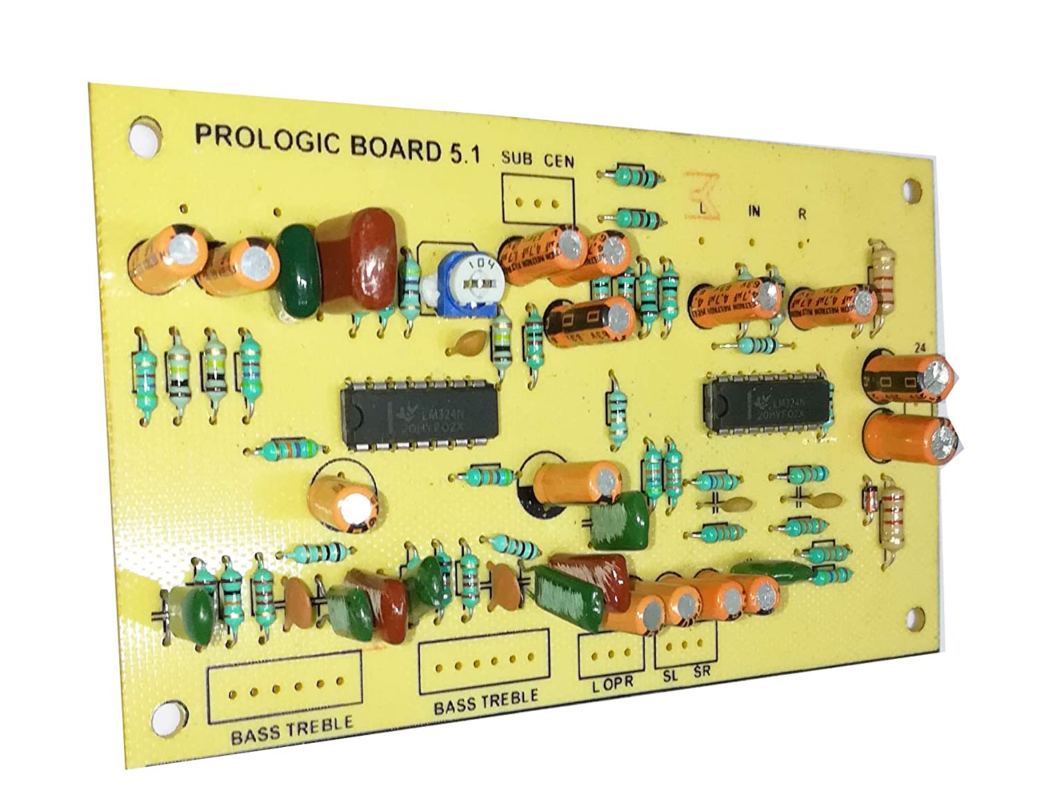
The first image showcases a Prologic board circuit diagram, likely associated with a PLC (Programmable Logic Controller). PLCs are widely used in industrial automation to control machinery and processes. Understanding the inputs and outputs of the PLC is fundamental. Inputs receive signals from sensors and other devices, translating real-world conditions into electrical signals that the PLC can interpret. Outputs, on the other hand, send signals to actuators, relays, and other devices, enabling the PLC to control machinery and processes. Key features to look for in such diagrams include the arrangement of input and output modules, the communication protocols used (e.g., Ethernet, Modbus), and the power distribution network. The diagram should clearly identify the function of each component and its connection to other parts of the circuit. Furthermore, understanding the addressing scheme used for inputs and outputs is essential for programming and troubleshooting the PLC.
The ability to interpret such a diagram is also important for safety reasons. Knowing the location of emergency stop circuits, safety interlocks, and other safety-critical components is paramount for preventing accidents and ensuring the safe operation of machinery. This involves tracing the wiring of these circuits and understanding their functionality in the context of the overall system.
5.1 Prologic Board Circuit Diagram - Brushly

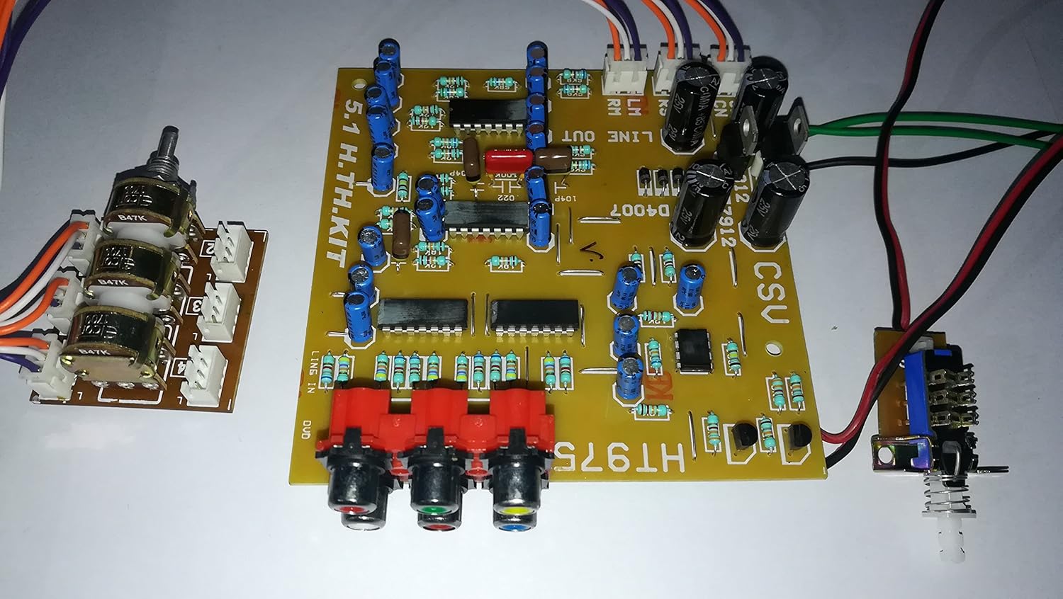
The second image depicts a 5.1 Prologic board circuit diagram, which is typically associated with audio systems. In 5.1 surround sound, there are five main channels (left, center, right, left surround, right surround) and a subwoofer channel (designated ".1"). The circuit diagram would illustrate the amplification stages, signal processing circuits, and connections to speakers. Understanding the signal flow within the diagram is essential for diagnosing audio problems, such as distortion, noise, or a lack of sound in one or more channels. Tracing the signal path from the input (e.g., DVD player, receiver) to the output (speakers) helps identify potential points of failure. Key components to analyze include operational amplifiers (op-amps), filters, and volume control circuits. The diagram should also show the power supply circuitry and how it provides power to the various components on the board.
For audio applications, it's crucial to pay attention to the impedance matching between different components. Impedance mismatches can lead to signal loss and distortion. The diagram may indicate the impedance values of different parts of the circuit, such as the input and output impedances of amplifiers. The diagram should also show the grounding scheme used in the system. Proper grounding is essential for minimizing noise and hum. Careful analysis of these diagrams allows for targeted repairs, upgrades, and modifications to audio systems, optimizing performance and ensuring a high-quality listening experience.
If you are looking for DIY 5.1 surround sound decoder (audio 5.1/ Dolby Prologic), this you've came to the right place. We have 25 Pics about DIY 5.1 surround sound decoder (audio 5.1/ Dolby Prologic), this like 5.1 Prologic Board Circuit Diagram - Brushly, 5.1 Prologic Board Circuit Diagram - Brushly and also Prologic Board Circuit Diagram Plc Outputs Inputs Features E. Here it is:
DIY 5.1 Surround Sound Decoder (audio 5.1/ Dolby Prologic), This
 in.pinterest.com
 5.1 Prologic Board Circuit Diagram - Brushly
 brushlyx.blogspot.com
 5.1 Prologic Board Circuit Diagram - Brushly
 brushlyx.blogspot.com
 5.1 Prologic Board Circuit Diagram - Brushly
 brushlyx.blogspot.com
 5.1 Prologic Board Circuit Diagram - Brushly
 brushlyx.blogspot.com
 5.1 Prologic Board Circuit Diagram - Brushly
 brushlyx.blogspot.com
 5.1 Prologic Board Circuit Diagram - Brushly
 brushlyx.blogspot.com
 Prologic Board Circuit Diagram Plc Outputs Inputs Features E
 eserowski4eqschematic.z14.web.core.windows.net
 Prologic Board Circuit Diagram Plc Outputs Inputs Features E
schematicvaradavi660.z21.web.core.windows.net 5.1 Prologic Circuit Diagram - Hd Audio Rush 5 1 Decoder Review : Audio
prologic shopee audio
5.1 Prologic Board Circuit Diagram - Brushly
brushlyx.blogspot.com 5.1 Prologic Board Circuit Diagram - Brushly
 brushlyx.blogspot.com
 Prologic Board Circuit Diagram Plc Outputs Inputs Features E
 manualblewynnessse.z21.web.core.windows.net
 5.1 Prologic Board Circuit Diagram - Brushly
 brushlyx.blogspot.com
 Prologic Board Circuit Diagram Plc Outputs Inputs Features E
 eserowski4eqschematic.z14.web.core.windows.net
 Bass Treble Circuit Diagram - Electronics Help Care
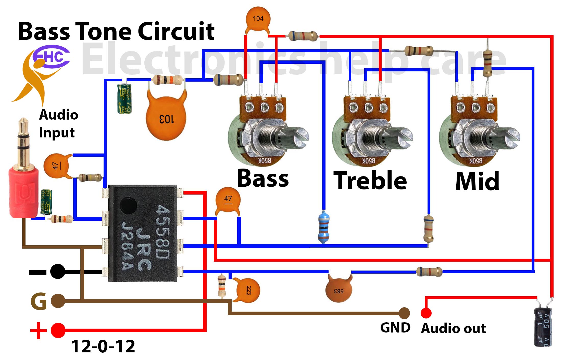 electronicshelpcare.net
 5.1 Prologic Board Circuit Diagram - Brushly
 brushlyx.blogspot.com
 5.1 Prologic Circuit Diagram - Hd Audio Rush 5 1 Decoder Review : Audio
 wiringdiagram81.blogspot.com
 prologic circuit schematics surround decoder
Prologic Board Circuit Diagram Plc Outputs Inputs Features E
 eserowski4eqschematic.z14.web.core.windows.net
 5.1 Prologic Board Circuit Diagram - Brushly
 brushlyx.blogspot.com
 5.1 Prologic Board Circuit Diagram - Brushly
 brushlyx.blogspot.com
 Prologic Board Circuit Diagram Plc Outputs Inputs Features E
 hlokehak9jschematic.z14.web.core.windows.net
 5.1 Prologic Board Circuit Diagram - Brushly
 brushlyx.blogspot.com
 5.1 Prologic Board Circuit Diagram - Brushly
 brushlyx.blogspot.com
 5.1 Prologic Board Circuit Diagram - Brushly
 brushlyx.blogspot.com
 5.1 prologic board circuit diagram. 5.1 prologic board circuit diagram. 5.1 prologic board circuit diagram